
|
This circuit is a simple amplifier of the audio signal comming out directly from a magnetic head of a cassete player (like the ones used for cars, before the CD era). The design is focusing on simplicity and not on generating a high fidelity output, which is also depending on the quality of the cassette (tape).
This amplifier differs from most audio amplifiers based on common opamps because it uses an LNA opamp (low noise amplifier), due to the fact the audio source has microvolt level (uV). Amplifying a uV voltage without adding internal noise is not an easy task. Note that the output of a microphone has a mV voltage level so it's easier to use common opamps for the amplification.
|
Showing posts with label Electronics. Show all posts
Showing posts with label Electronics. Show all posts
Friday, December 26, 2014
Simple cassette player amplifier
Saturday, January 18, 2014
Weird legged PCB Robot

|
This is a simple but weird robot build entirely with veroboards (stripboards).
The robot is standing on two free running wheels and it has two legs that are pushing it like a small cart. Characteristics
|
Programming this weird robot to move is not an easy task. The required procedures are not so simple, like in the case of a wheeled robot (or even on a three servo robot). The number of servos is enough to make the required walking procedures complicated. Using a different procedure for going forward, turning left and right is not the best way, because you will soon overflow the microcontroller's rom (EEPROM), due to the complexity of the routines. A better approach is to write a procedure that calculates the angles of each servo by solving the inverse kinematic problem for both legs. However this requires some sophisticated math.

Thinking all that, I was searching a way to make the motion routine more generic, to cover all of these cases (forward, left, right, backwards etc). The simplest way is to save all the necessary PWM values to memory. The trick here is to split each motion in frames. Each frame will have the PWM values of all the servos (in our case, six). The only thing you need, is to save the number showing the total frames in the motion scenario. By addressing to the start of each scenario, it is possible to write a generic motion procedure.
For example lets take a look on how we should save the PWM values for a going forward motion scenario.
Forward0 DATA 2
Forward1 DATA Word 450, Word 550, Word 450, Word 850, Word 880, Word 600
Forward2 DATA Word 450, Word 470, Word 600, Word 850, Word 800, Word 750
The PWM values
are the result of trial and error and they will be different to
your robot.
In this case we split the scenario in two frames
(Forward1 and Forward2). Forward0 shows the total number
of frames (in our case, two). All these numbers have a meaning.
In my case this is the format of each frame
Format: Total Steps (byte)
Right Shoulder (Word) -> Right Arm (Word) -> Right Elbow (Word) ->
Left Shoulder (Word) -> Left Arm (Word) -> Left Elbow (Word)
The first byte is
the total number of the frames. The six word numbers in each
frame are for the right and left leg respectively.
So in order
the robot to execute the movement, the only thing we have to do is
point the address (word) variable to the starting address
of each movement. In our case:
address = Forward0
GOSUB Move
where "Move" is the generic motion subroutine. Now, if we want to turn left will write something like that
address = GoRight0
GOSUB Move
supposing we have saved in memory the PWM values of the specific movement. For example:
GoRight0 DATA 2
GoRight1 DATA Word 330, Word 550, Word 500, Word 700, Word 880, Word 600
GoRight2 DATA Word 330, Word 500, Word 600, Word 700, Word 800, Word 700
Once we have decided they way we will save the PWM values of the servos in robot's memory, we can go on writing the generic motion subroutine. Despite the complicity the motion subroutine is quite simple
Move:


     ' Generic motion
     subroutine for the weird legged robot.
  '
  ' First read total frames.

       READ address,bdata

       address = address + 1

       FOR j=1
     TO bdata


     ' Send total 21 pulses for each servo.

     ' 21 pulses are
     enough to complete the motion (of one frame).

     ' You may need to change it for different type of servos

         FOR i=0
     TO 20

           PAUSE 3


     ' Read PWM value
     for right shoulder and send the pulse.

           READ address,Word
     wdata

           PULSOUT
     right_shoulder,wdata

           '
     Read PWM value for right arm and send the pulse.

           READ address +
     2,Word wdata

           PULSOUT
     right_arm,wdata

           '
     Read PWM value for right elbow and send the pulse.

           READ address +
     4,Word wdata

           PULSOUT
     right_elbow,wdata


     ' Read PWM value
     for left shoulder and send the pulse.

           READ address +
     6,Word wdata

           PULSOUT
     left_shoulder,wdata

           '
     Read PWM value for left arm and send the pulse.

           READ address +
     8,Word wdata

           PULSOUT
     left_arm,wdata

           '
     Read PWM value for left elbow and send the pulse.

           READ address +
     10,Word wdata

           PULSOUT
     left_elbow,wdata

         NEXT


      ' Go to next
     frame

         address = address + 12

       NEXT

     RETURN
First we go to the address stored in the variable
address and we read the total
number of frames (variable bdata).
Each frame is consisted from 12 bytes total (6 word values).
Next we read the six word PWM values with the order we discussed
earlier and simultaneously we send the pulses to the servos.
Each stored value is the duration of the pulse we must send to
the appropriate servo. In reality each value is the duration in
milliseconds divided by the factor two, because 2ms is the step
of Basic Stamp 2.
For each frame we send the same PWM values to
the servos for 21 times (meaning we send total 21 pulses to
each servo). This is important or else the motion will not
be able to complete (servos require a number of pulses to
complete their movement to the desired position).
When
sending of all these pulses is completed, we go to the address
of the next frame (if this exists) and we repeat the
process. The reason we increase the value of the variable
address by 12 is because 12
bytes are stored in each frame, as we said earlier.
Detection of sound direction
This robot has the ability to detect sound direction. That means it can follow a sound source.
Unfortunatelly Basic Stamp 2 doesn't have analog inputs like arduino (remember that arduino is newer). This means that for Basic Stamp 2 we don't have the information of how much left or right the sound is coming from.
In the following picture you can see the schematic diagram of the circuit that is build in the weird robot

The circuit is simple enough. The signal of each microphone is amplified by the transistor based pre-amplifier and then passes through the peak detector. The next stage is the two subtraction amplifiers. The first one is amplifying the difference between the left and the right signal and the second one the difference between right and left. The outputs of the subtraction amplifiers are then compared with a threshold voltage (one for each calculated difference). The threshold voltages are also calibrating the sensitivity of the circuit
Why we are calculating these differences?
Generally we need three distinct states. i) The sound is coming from the left side ii) The sound is coming from the right side and iii) No sound detected. Clearly with arduino things would be much easier if we used two of the analog inputs.
There are totally three trimmers to adjust sensitivity. The trimmer of the one preamplifier is used to adjust the voltage differences to zero (or almost to zero) when the sound is coming in front of the robot.
Coding
In order Basic Stamp 2 to decide about the direction of the sound, a small program must be written in PBasic. The complete detection process is typically one simple subroutine
' -----[ Subroutine - Get_Sound_Sensors_Status ]---------------------------------
Get_Sound_Sensors_Status:
SoundRightSensor = SoundRightSensor + IN5
SoundLeftSensor = SoundLeftSensor + IN6
iCountSound = iCountSound + 1
IF iCountSound = SoundFilterWindow THEN
iCountSound = 0
LeftMIC = 0
RightMIC = 0
IF SoundLeftSensor<SoundRightSensor THEN LeftMIC = 1
IF SoundRightSensor<SoundLeftSensor THEN RightMIC = 1
SoundRightSensor = 0
SoundLeftSensor = 0
ENDIF
RETURN
We must also define the following constants and variables
SoundFilterWindow CON 50
iCountSound VAR Byte
SoundLeftSensor VAR Byte
SoundRightSensor VAR Byte
LeftMIC VAR Bit
RightMIC VAR Bit
The status of the left microphone is stored to LeftMIC (if is one, the sound is coming from the left). Variable SoundLeftSensor is actually showing how many times is Vleft > Vright + Vthres (Vthres comes from hardware. Meaning it depends on the position of the comparator's trimmer, which is adjusting the sensitivity).
Same things for the variable RightMIC, regarding the right microphone. Variable SoundRightSensor is showing how many times is Vright > Vleft + Vthres
The constant SoundFilterWindow is showing how many measurements the program must do, in order to make a reliable result. The value will come out from the test and will be deferent in your case.
In the following video you can see the robot in a simple test. In order to visually see which decision the robot made, regarding the direction of the sound, I connected two LEDs
Soccer and Sumo Robot???

|
OK, this is a new design I am working on. It's a small robot with a kicking mechanism, a grip and a lot of other cool stuff (e.g. BlueTooth and the ability to control it with an Android app, the ability to charge it to a charging base and much more). This is the prototype and I built it for the tests. Curently I am working on the new improved PCB's
It is Arduino based I have also some thoughts of implementing a txtzyme style language or a visual style programming using Blockly (or maybe I will combine those two techniques) |
Monday, August 27, 2012
Simple Volume Unit meter (VUmeter)

|
This is by far the simplest VUmeter you can build. It is based on a single chip. A volume unit (VU) meter or standard volume indicator is a device for displaying the level of any voltage signal source (which is usually a sound signal).
Connect the module to the output of any amplifier (or preamplifier) and set the trimmer where all LEDs are lighting, when the volume of the amp is at maximum (or at least at that point, where you want all LEDs to light). |
Monday, January 3, 2011
Convert a webcam to infrared

|
This is a very simple project and it doesn't require a circuit board to be made. We are going to convert a cheap web camera to an infrared camera, capable of viewing in the dark. You can use the IR camera for to a home security system (surveillance system).
The only thing you need is a infrared light source witch is invisible to the naked eye. But this is the subject of another project!
|
Monday, May 10, 2010
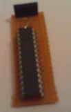
BasAVRa LiTe

|
BasAVRa LiTe is an alternative programming board for the famous Basic Stamp II by Parallax (OEM
version). We have already see how to make our own homemade
Basic stamp 2 board of education using the OEM chip, in the
article BS2 programming board.
BasAVRa LiTe goes one step further by replacing the wired serial connection with a wireless Bluetooth to serial connection. With BasAVRa LiTe you can program and control Basic Stamp 2 from your computer without using wires and from great distance (e.g. from the next room). |
Thursday, July 16, 2009
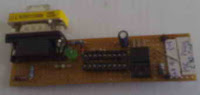
RS232 to TTL level converter

|
Perhaps this is the most famous RS232 to TTL level converter. When launched by MAXIM, it become so popular that several clones acquired as the years went by. This project shows how it is possible to implement a small module to interact easily with devices which support the asynchronous serial interface (TTL levels).
|
Monday, April 6, 2009
IR remote control tester circuit

|
This is a simple and small circuit you can build in order to test infrared remote controls, coming from audio and video devices (e.g. television, DVDs, VCRs and more). You can also use it to test devices which are using the famous IrDA protocol.
|
Wednesday, November 12, 2008
In circuit AVR programmer (ISP)

|
Perhaps this circuit is the simplest AVR programmer you can build. Its great advantage is the ability to program almost any AVR microcontroller, without the need to remove it from the circuit in which is connected (in circuit programming).
|
Wednesday, January 9, 2008
PIC16F876/3 adaptor for the simple PIC programmer
|
This adaptor extends the possibilities of the simple PIC programmer, to be able to program PIC micros like PIC16F876, PIC16F876A, PIC16F873 and PIC16F873A. Simply connect it to the main board.
|
A simple programmer for PIC microcontrollers
|
Perhaps this circuit is the simplest programmer for PIC microcontrollers you can build. It is connected to serial port of your PC and it has a very similar design with the SI-Prog programmer for the AVR microcontrollers. With the help of adaptors you can extend the possibilities and program more PIC microcontrollers.
|
Friday, July 6, 2007
Simple pulse generator with accurate frequency 1Hz

|
This circuit is ideal for clocks and anything that has to do with time measurement. The output pulse comes every one second with great accuracy (without being affected by environmental interferences or time). Its accuracy is based on a quartz crystal oscillator, which guaranties that your clock will not desynchronize.
|
Friday, November 18, 2005
R/2R ladder DAC

|
This is a famous digital to analog converter that uses a resistor ladder network in order to convert the signal from digital to analog. It has 8bit resolution, but you can easily increase it, if you follow the pattern. The circuit is very reliable and it doesn't require a lot of time to build it.
|
Tuesday, September 20, 2005
Serial ADC for BS2
 |
Connect National's Semiconductors serial analog to digital converter ADC0831 to Basic Stamp 2 and digitize your analog data. The required program couldn't be simpler (literally only 3 commands).
|
Saturday, July 30, 2005
Voltage to current converter (V-I converter)

|
This circuit is one of the simplest voltage to current converters to drive low loads. In this example a small 0,25 Watts speaker, with 8Ω resistance, is driven. It is suitable for microcontroller designs or any other circuit that uses PWM (TTL logic). You can use it for analog signals as well.
|
Sunday, June 26, 2005
Stereo amplifier with KIA6210AH

|
This is a HiFi stereo amplifier based on KIA6210AH dual audio power amplifier chip, with output power 2x22 Watts (this is the circuit's true output power and not the sound power. As you can see is fairly high). KIA6210AH chip is not hard to find. Personally, I dig it out from an old car cassette player.
|
Monday, April 25, 2005
A simple SI-Prog

|
With the following circuit you can easily program the AVR microcontrollers AT90S1200, AT90S2313 (or ATtiny2313), AT90S8515 and AT90S4414, using the freeware programmer PonyProg by Claudio Lanconelli. You can download the program for free from the author's website (www.lancos.com/prog.html).
|
Sunday, January 9, 2005
Sound detection circuit with variable sensitivity

|
This is a simple circuit that can detect sounds by using a common condenser microphone. Sensitivity is variable . The circuit's output becomes High each time a sound is detected, otherwise it is in low level. You can use it in simple robots for sound responding (e.g. reaction -> when you clap your hands). This circuit recognize human voice as a common sound (you can't use it for voice recognition).
|
Tuesday, December 21, 2004
BS2 programming board (board of education)

|
Build your own low cost Basic Stamp II board of education by parallax. The "trick" here is to buy the OEM version of Basic Stamp 2 from parallax (Basic Stamp 2 interpreter chip DIP). This will keep the cost very low but there's a catch. You must be able to solder electronic components on a Veroboard (StripBoard).
|
Subscribe to:
Posts (Atom)