|
BasAVRa LiTe is an alternative programming board for the famous Basic Stamp II by Parallax (OEM
version). We have already see how to make our own homemade
Basic stamp 2 board of education using the OEM chip, in the
article BS2 programming board.
BasAVRa LiTe goes one step further by replacing the wired serial connection with a wireless Bluetooth to serial connection. With BasAVRa LiTe you can program and control Basic Stamp 2 from your computer without using wires and from great distance (e.g. from the next room). |
With BasAVRa LiTe you can exchange data wirelessly (via Bluetooth) between the computer and Basic Stamp 2, by using the PBasic commands DEBUG and DEBUGIN. You don't have to use a third party transceiver.
|
Because BasAVRa LiTe is not a product of Parallax you can not
buy it from their website (www.parallax.com).
Of course you will buy Basic Stamp 2 OEM chip.
|
Keep in mind that you can not use parallax Basic Stamp Editor to program BasAVRa LiTe. You must use BasAVRa Editor instead. This action has no affect to your PBasic programs, because BasAVRa Editor uses Basic Stamp tokenizer library (with simple words your PBasic code stays the same).
The graphical user interface (GUI) of BasAVRa Editor is very
close to Parallax's Basic Stamp Editor, so it will not be difficult
to use.
Download the program from this page:
BasAVRa Editor
|
In order BasAVRa LiTe to work, you need to download the
appropriate firmware to ATTiny2313 (see
below). To do that you need a programmer supporting
ATTiny2313 (e.g. STK500).
|
If you don't have such a programmer and you don't want to buy a new
one, there is an alternative. You can make your own. If you search
the internet you will find many implementations and schematics, but
I recommend building the one presented in this page:
A simple SI-Prog.
I have included a
simple tutorial on how to download the firmware using the previous
programmer (see below), to help you out.
Components
- Four 10KΩ resistors (1/4 Watt).
- Four 4.7KΩ resistors (1/4 Watt).
- One 180Ω resistor (1/4 Watt).
- One 240Ω resistor (1/4 Watt).
Attention: Don't replace it with another resistor. - One 390Ω resistor (1/4 Watt).
Attention: Don't replace it with another resistor. - One 1000μF electrolytic Capacitor (16 Volts).
- One 330μF electrolytic Capacitor (16 Volts).
- One 470μF electrolytic Capacitor (16 Volts).
- One 1μF electrolytic Capacitor (16 Volts).
- Seven 100nF capacitors.
- One transistor BC557B.
- Two 1N4148 diodes. Note: You can replace these diodes with two BAT85 Schottky diodes.
- A common red LED.
- One 20MHz piezoelectric crystal.
- One 8MHz piezoelectric crystal.
- One Basic Stamp 2 interpreter chip (DIP).
- One 24C16 memory chip (I2C).
- One AVR ATtiny2313 chip.
- One LM2940 LDO voltage regulator (with the appropriate cooler, if you plan to drag more than 500mA).
- One LM317 voltage regulator (TO-92 package).
- One Bluetooth to serial converter module. (You can use the module constructed by Sure electronics or anything else compatible with it). Note: Remember BasAVRa works with 9600 baud. Buy a Bluetooth module supporting the previous baud rate.
- One ALPS button (a digital push button. Not switch) for a manual reset feature.
- One power jack.
- (Optional) Two single row female pin headers (one with 16 pins and one with 13. If you have headers with more pins, just cut them). You need 16 pins for the I/O ports and 13 for power (look at the schematic).
- (Optional) One female double row pin header with 20 pins totally (If you have with more pins, just cut it).
- (Optional) One small breadboard.
- A 28 pin DIP socket (for BS2 chip).
- A 20 pin DIP socket (for the AVR chip).
- A 8 pin DIP socket (for the memory chip).
- A Veroboard - StripBoard (or a PCB but I don't include a layout. Make your own).
- Wire for connections
- Solder and soldering iron
Also you will need a stabilized 12V, 9 Volt or even 6Volt external power supply, due to the low dropout voltage regulator. I recommend using six NiMH rechargeable batteries.
In the following picture you can see the general idea behind BasAVRa LiTe and how, approximately, each unit costs (Note: The prices in the picture are old and now may vary. Probably they would be cheaper)
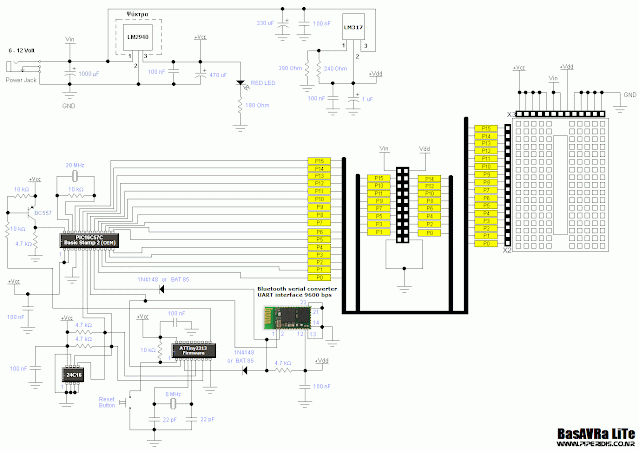
Here is the schematic diagram of BasAVRa LiTe (Click on the picture to enlarge).
Attention: Solder the 100nF capacitors as close to the ICs power supply pins as possible. Same thing with the piezoelectric crystals. Solder them, as close as possible to the XTAL pins of the ICs. Don't replace the resistors of the LM317 regulator with other values. That regulator is used to generate the necessary 3.3Volts for the Bluetooth module. If you don't have the low-dropout voltage regulator LM2940, you can replace it with the standard 7805 regulator.
Some Notes for the Bluetooth module
Initially, I used the Bluetooth to serial converter designed by Sure electronics. However BasAVRa LiTe will work with any Bluetooth to serial converter, as long as it's compatible with the one designed by Sure (and by compatible I mean, having the same pinout and baud rate). Almost all the converters you can find are compatible and they will work without any problems.
Bluetooth
to serial converter
UART interface 9600 bps by Sure
electronics
F.A.Q.
|
Question:
Can I use a different type of Bluetooth module, even if it has no
the same pinout or baud rate like the one designed by Sure
electronics?
Answer:
Yes. If your Bluetooth module has a different pinout, you must
take care on how you'll connect it in the circuit. Remember that
pin 1 (see the schematic) is UART-TX,
pin 2 is UART-RX, pin 12 is the power
supply (usually 3.3V) and pin 13 is ground
(GND).
If your Bluetooth module has a different baud rate, then you can
hack the source code of the firmware (see below). Search
the code for the line $baud
= 9600 and replace the number with
the baud rate of your Bluetooth module.
Attention: If your Bluetooth to serial converter has a
high baud rate (e.g. 56700) then you may have to replace
the 8MHz crystal of ATtiny2313 with a different value, to
eliminate baud error. If you do replace the piezoelectric
crystal, don't forget to change the source code too (find for
the line $crystal
= 8000000 and change the number
with
the new crystal's value. Value is in Hz).
Note: With most Bluetooth to serial converters you can
set the baud rate to the desired value (read manufacturer's
documentation).
|
Downloading the firmware to ATTiny2313 (Only for the first time of use)
In order BasAVRa LiTe to work, you need to download the firmware to ATTiny2313. You need to do this only once.
Of course you will need a programmer to download the code. You can use whatever programmer, supporting AVR microcontrollers, you like (e.g. STK500). If you don't have a programmer then you can buy a new one, or you can build one by yourselves.
I recommend the simple SI-Prog programmer presented in this site. Is very easy to build and it has a low total cost (close to zero if you already have the necessary parts). You also need to download and install PonyProg2000 from the aythor's website (www.lancos.com/ppwin95.html).
Here I will describe the downloading procedure in few steps, supposing you have built the simple SI-Prog.
Step 1: First download the hex file of the code (firmware). BasAVRa LiTe firmware
Step 2: After unzipping the file, open PonyProg2000 Step 3: From menu select "Device" → "AVR micro" → "ATtiny2313" Step 4: Remove ATTiny2313 from BASAVRa LiTe and place it on the programmer. Then connect the programmer to your computer's serial port. Power on the device. From menu select "setup" → "Interface setup..." and the I/O port setup window will pop-up.
Select the serial port you connect the programmer (usually COM1). From the dropdown list select "JDM API" or "SI-Prog API". The window must look like the above picture.
Attention: SI- Prog and PonyProg2000 require a physical serial port on your computer. IT WILL NOT WORK with a USB to Serial converter.
Step 5: Select "Command" → "Security and Configuration bits..." and the Security and configuration bits window will pop-up, after automatically reading the device. Uncheck all the boxes like you see in the picture below. Press the button "Write". Then Press "OK"
Step 6: Now we are ready to load the hex file. Select "File" → "Open Device File...". Browse to the directory you unzipped the hex file and press "Open" Step 7: Now we are going to program the chip. Select "Command" → "Write All" and press yes to the pop-up message. Now you will see the programming procedure initialized. First the program will write the code and then will automatically verify it. Step 8: If you see the write successful notice, then the procedure has been completed. Now, the firmware has been downloaded and your chip is ready to go. You don't have to repeat these 8 steps anymore.
Note: If you have a write error message please try again. Make sure you have powered the device on during the whole procedure.
Source Code
BasAVRa LiTe is Open Source and you can download the code
from the following link. The program is written with the demo
version of BASCOM-AVR by MCS
Electronics.
You can download directly BASCOM-AVR Demo for free
from this link:
BASCOM-AVR Demo
Download BasAVRa's LiTe source code: BasAVRa LiTe
|
Note: You can compile the code with BASCOM-AVR Demo, but
remember that the code for the flash and eeprom are saved to
separate files. The hex file is for flash and the eep file for
the eeprom. You must download both of them to the chip or it
will not work.
To save you time from the extra work, I have created a single
hex file, ready to download it to the chip (see above).
|
Pictures
In the following picture you see the BasAVRa LiTe, build on a Veroboard. You can't see the power supply section, because it is build on another Veroboard. Also I didn't add the small breadboard (but I will add it in the future).


No comments:
Post a Comment